Installation of energy storage systems in combination with RES and CHP plants by self-producers with real-time net billing
Frequently Asked Questions
The installation of storage systems in combination with stations of self-producers/self-consumers (hereinafter “self-producers”) with real-time net billing is provided for under Ministerial Decision No. ΥΠΕΝ/ΔΑΠΕΕΚ/93976/2772 (GG B 5074/5.9.2024).
A storage system refers to an electrochemical battery system for the storage of electrical energy (BESS: ‘Battery Energy Storage System’). It consists of: (a) power converter(s)[1] capable of absorbing and injecting active and/or reactive power; (b) batteries connected on the DC side of the converter; (c) electrical equipment for interconnection (switches, cabling, protection devices, etc.), and (d) a control and monitoring system.
[1] When a power electronics device is used to transfer power in both directions, i.e. from and to the DC side, the term “converter” is used. This is in contrast to the term “inverter”, which is used when power is transferred only from the DC side, as is the case in the connection of photovoltaic (PV) modules.
The possible operating modes of a storage system in combination with a RES plant in a consumption installation are described in the table below.
|
S/N |
Injection into the storage system Grid | Absorption from the storage system Grid |
Operating mode |
|
| Operating restrictions on the storage system | 1. | X | X | The batteries only absorb energy from the plant and only deliver it to the loads in the installation. |
| 2. | √ | Χ | The batteries absorb energy only from the plant and deliver it to the loads or to the grid. | |
| 3. | Χ | √ | The batteries absorb energy from the plant or the grid and deliver it only to the loads. | |
| Operation without restrictions | 4. | √ | √ | The batteries absorb energy from the plant or the grid and deliver it to the loads or the grid |
Operating mode (4), since it allows the absorption from and re-injection into the Grid of the stored energy, may be applied only in cases where the injected energy is remunerated at market prices, unlike operating modes (1) and (2), which may be applied even when the injected energy is remunerated under a support scheme (operating aid). Operating mode (3) may be applied to a plant connected to the Interconnected System that does not inject energy into the Grid (zero feed-in). For plants connected to the Non-Interconnected Islands, only operating mode (1) is permitted.
It is noted that during operation of the plant, under the implemented control strategy, the aggregate power injected into the Grid from the energy storage system and the power generated by the plant’s generation units and injected into the Grid must not exceed the Agreed Capacity (AC) of the supply connection. Accordingly, the absorption power of the energy storage system together with the other loads of the installation must not exceed the Agreed Capacity (AC) of the supply connection. Furthermore, the real-time injection of power into the Grid from both the generation units and the storage units must not exceed the maximum generation capacity specified in the self-producer’s Connection Agreement.
For the submission of applications for net billing with remuneration of electrical energy, completion of the field “Remuneration method for injected energy” is required. Based on this selection, the field “Operating mode of the energy storage system” is automatically completed by the application. More specifically:
| Remuneration method for injected energy | Operating mode of the energy storage system |
| Remuneration with operating aid (support scheme) | Without the possibility of absorbing energy from the Grid |
| Direct participation in the market | With the possibility of absorbing and injecting energy into the Grid |
In addition, for self-producers under net billing without remuneration of electrical energy, the field “Operating mode of the energy storage system” is automatically completed with the value “With the possibility of absorbing and injecting energy into the Grid”, whereas for zero feed-in plants this field takes the value “With the possibility of absorbing energy from the Grid.”
These options are reflected in the Final Connection Offer (FCO), where required, and in the Connection Agreement of the plant. In this way, the operating framework of the energy storage system is indicated to the self-producer. For example, an energy storage system in a zero feed-in plant may absorb energy from the Grid; however, it must not inject energy into the Grid. By contrast, for a plant remunerated through participation in the market, the option “With the possibility of absorbing and injecting energy into the Grid” provides the self-producer with the flexibility to define the operation of the energy storage system according to their needs. Accordingly, in all other cases, the self-producer is required to comply with the condition applicable to the plant and, within this framework, to adjust the operation of the energy storage system as deemed appropriate, in accordance with what is described in the answer to the relevant question 3.
Through the operation of the energy storage system in net-billing facilities, it is possible to increase self-consumption of the energy produced by the generation plant and consequently reduce the absorption of energy from the Grid at the self-producer’s installation. For example, in combination with a PV plant, an energy storage system could store surplus energy during midday hours and supply it to the self-producer’s loads during evening hours, i.e. during the hours when the self-producer would otherwise need to absorb energy from the Grid. As a result of this operation, an additional financial benefit is created for the self-producer, since the absorption of energy from the Grid is reduced.
It is noted that an increase in self-consumption of the energy produced by the generation plant could also be achieved through “smart” load management, i.e. by shifting the operation of consumption loads so as to achieve simultaneity between consumed energy and energy produced by the plant.
Furthermore, the integration of an energy storage system in an installation enables a consumer to absorb energy from the Grid during low-tariff hours for consumption during periods when energy would otherwise need to be absorbed at higher prices.
Finally, the absorption of energy produced by the generation plant by the energy storage system, with the aim of injecting it into the Grid at a later time, is intended to allow the sale of energy at a higher market price.
During the operation of the generation plant and the energy storage system, the storage system absorbs energy from the generation plant, and this energy is used to supply part or all of the self-producer’s loads.
For the management of energy within the self-producer’s installation, an “energy flow direction sensor” (or “smart energy meter”), single-phase or three-phase as applicable, with or without current transformers (CTs), is installed at the point of connection of the self-producer’s installation. Depending on the direction of energy flow (injection/absorption), it sends a command to the converter control system to charge or discharge the batteries.
By way of example, the following energy management strategy could be adopted:
- when energy flows from the Grid into the electrical installation—such as when the generated energy is insufficient to cover the self-producer’s loads—the batteries are discharged to supply the loads, in order to reduce absorption from the Grid.
- when there is surplus generated energy and energy flows out of the electrical installation, the batteries are charged from the generation plant so that the stored energy can be used at a later time when demand is higher.
- in the case of high demand, energy may be supplied in real time from both the generation plant and the batteries.
- in the case of low demand and increased generation, or when the batteries are fully charged, the surplus energy from the generation plant may be injected into the Grid.
If the batteries have sufficiently large capacity to absorb the entire surplus energy from the generation plant and/or the plant receives a command from the energy management system to reduce or cease production, the installation may operate without injecting energy into the Grid (zero feed-in). In this case, connection of the plant to a congested Grid is possible, provided that the congestion is due to exceeding the nominal capacity of Grid components or exceeding the desired voltage limits at Grid nodes.
The energy flow direction sensor is a high-accuracy meter with a high measurement sampling rate. Certification by the HEDNO laboratory is not required. However, the following requirements must be met, as evidenced by the manufacturer’s certificates or technical datasheets:
- Measurement error <1%
- Measurement sampling every 500 msec or less
- Capability for wired communication with the converter (e.g. RS485)
It is noted that upstream of the energy flow direction sensor (on the Grid side), there must be a main means of disconnection and isolation of the installation.
For certification of the operating mode of the energy storage system in relation to the Grid, the self-producer is required to submit to HEDNO a Technical Description accompanied by an electrical schematic and the manufacturer’s technical manuals for the converter and the energy flow direction sensor. In addition, the self-producer commits, by means of a Solemn Declaration under Law 1599/1986, that throughout the entire period of operation of the installation, the settings of the energy storage system will not be modified.
During commissioning of the energy storage system, HEDNO may carry out appropriate tests to verify the operating mode of the energy storage system. During operation, HEDNO may also monitor and correlate the metering data of the energy produced and injected.
If it is found that the approved operating mode is being violated, HEDNO may deactivate the self-producer’s connection to the Grid.
During the commissioning of a generation plant combined with an energy storage system, HEDNO, in addition to the inspections, tests and measurements required for the commissioning of the generation plant, carries out the following tests for the energy storage system:
- Disconnection protection tests of the energy storage system, where a separate converter is installed for the storage system.
- Verification of non-injection of energy into the Grid and/or non-absorption of energy from the Grid, where operating restrictions have been defined.
The Operator may also require the performance of tests and measurements over a trial operation period, in accordance with Article 79(5) of the HEDN Code.
The energy storage system forms part of the self-producer’s Internal Electrical Installation, i.e. it is installed “behind the meter”. Consequently, responsibility for its installation and for its safe and uninterrupted operation lies with the self-producer and the legally responsible engineer. The installation must comply with the applicable ELOT 60364 standard as well as IEC 62933-5, under which potential risks arising from the operation of the energy storage system must be identified and the necessary measures taken to mitigate or eliminate them. The application of more specific standards and rules depends on the type of batteries used; for example, for lead-acid batteries, compliance with EN 50172 is mandatory. It is clarified that during commissioning, only those elements of the installation that affect the operation of the Grid and other connected users are inspected. In all cases, responsibility for the proper operation of the entire installation lies with the self-producer and the legally responsible engineer.
The following conditions apply for the connection of the energy storage system to the self-producer’s installation:
- Converters with rated power up to 5 kVA, or converters of higher rated power that cannot inject power exceeding 5 kVA, may be connected to a single phase. Otherwise, a three-phase connection to the Grid is required.
- In three-phase systems, the batteries may be connected either via a three-phase converter or via three single-phase converters[1], which must communicate with each other and operate as a single three-phase converter.
- When single-phase converters are used in three-phase systems, the power of the energy storage system connected to the three phases should be distributed as evenly as possible.
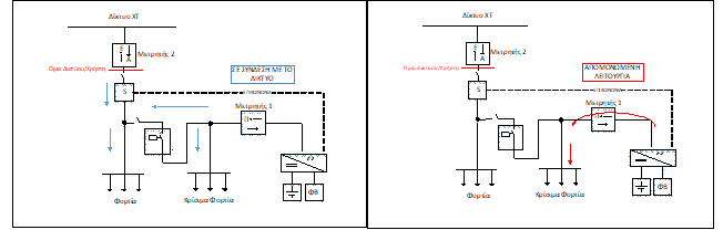
- Where the energy storage system is combined with a PV plant, the batteries and the plant may be connected to the self-producer’s internal electrical installation either via the same power converter (Figure 1b) or the batteries may be connected via a separate power converter (Figure 1a and Figure 2). The configuration using a separate converter may be applied to the connection of any RES or CHP plant.
- For LV supplies Nos. 5, 6 and 7 (Agreed Capacity of 85 kVA, 135 kVA and 250 kVA respectively), installation of the generation plant in combination with the energy storage system with a direct outgoing feeder to the Main Distribution Board of the installation is permitted.
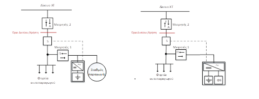
(a) (b)
Figure 1: Indicative simplified single-line diagram of an LV electrical installation as configured (a) after connection of a generation plant and batteries via separate converters (AC-coupled), and (b) after connection of a PV plant and batteries via the same converter (DC-coupled). The dashed line indicates communication between the energy flow direction sensor (S) and the converter management system. The diagram does not show the switching and protection devices of the supplied electrical installation, nor those of the generation plant and batteries, nor the Grid isolation system for off-grid operation.
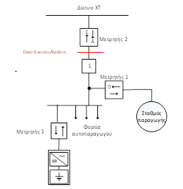
Figure 2: Indicative simplified single-line diagram of an LV electrical installation as configured after connection of a generation plant and batteries via separate converters (AC-coupled), with the energy storage system connected to the Main Distribution Board of the installation. The dashed line indicates communication between the energy flow direction sensor (S) and the converter management system. The diagram does not show the switching and protection devices of the supplied electrical installation, nor those of the generation plant and batteries, nor the Grid isolation system for off-grid operation.
[1] In particular, in three-phase systems where, under certain conditions, installation of a single-phase PV inverter is permitted, connection of a single-phase battery converter on the same phase is also permitted.
In cases of power supply interruptions from the Grid, isolation of the installation—or part of it—from the Grid is permitted, and operation may continue with supply from the energy storage system and/or the generation plant.
During isolated (off-grid) operation, a fundamental requirement is that there must be no connection to the Grid. In other words, an isolated “island” must be created within the installation, consisting of the loads (critical or all loads) and the energy sources. Isolation shall be achieved by means of a device that is recommended to disconnect the phase conductor(s) and the neutral conductor, regardless of the earthing system used (TT or TN). Indicative configurations showing the position of the isolation device are illustrated in the figures below.
In particular, where a hybrid PV/battery inverter is used that provides a second (emergency) output for critical loads (Figure 3.c2), this output must not supply loads during normal operation, so that the generation meter correctly measures the produced energy.
During both Grid-connected and isolated operation, the safety requirements applicable to the installation under ELOT 60364 are certified through submission of the Installer’s Declaration (YDΕ) and are, evidently, the responsibility of the installation user[1].
a. Isolated operation with supply of all loads from the energy storage system and the PV plant
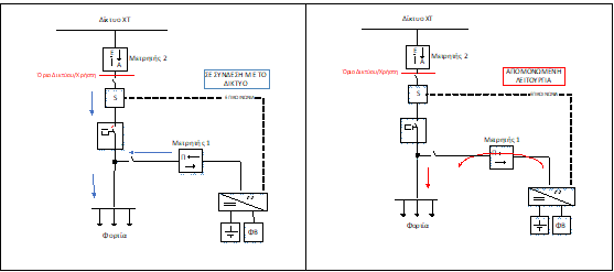
b. Isolated operation with supply of all loads from the energy storage system
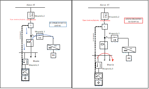
c. Isolated operation with supply of critical loads from the energy storage system and the PV plant
c1. Critical loads connected to a separate distribution board
c2. Critical loads connected to the Main Distribution Board of the electrical installation
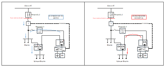
Figure 3: Indicative simplified single-line diagrams of an LV electrical installation as configured after connection of a PV plant combined with an energy storage system, with capability for isolated (off-grid) operation. In diagram c2, the sub-board with the two relays is indicative. Changeover could also be achieved by means of a three-position changeover switch (1-0-2).
[1] It is verified that the installation can operate safely using only local generation and storage, i.e. that sufficient fault current is available to ensure the operation of protective devices
For determining the maximum power of the energy storage system converter, the rated power of the storage system converter (in kVA) must not exceed the rated power of the generation plant (in kW). This limitation may be applied only where a separate (independent) converter exists for the energy storage system.
If no commercially available converter has a rated power less than or equal to the rated power of the generation plant, installation of a converter with higher rated power is permitted, provided that a permanent operating limitation is imposed up to the maximum permissible power level. This must be substantiated by type-test certificates for reduced rated power, issued by a recognized certification body.
In all cases—whether the batteries are connected to an independent converter or to a hybrid converter—under the implemented control strategy, the aggregate power injected into the Grid from the energy storage system and the power generated by the plant’s generation units and injected into the Grid must not exceed the Agreed Capacity (AC) of the supply connection. Accordingly, the absorption power of the energy storage system together with the other loads of the installation must not exceed the Agreed Capacity (AC) of the supply connection. Furthermore, the real-time injection of power into the Grid from both the generation units and the storage units must not exceed the maximum generation capacity specified in the self-producer’s Connection Agreement.
It is noted that no limitations are imposed on the energy capacity (kWh) of the energy storage system.
Example 1: In an LV installation with an agreed capacity of 135 kVA, a PV plant of 100 kW is installed with the ability to inject 100 kW into the Grid. The energy storage system with an independent converter to be installed must have a rated power less than or equal to 100 kVA. Since the commercially available converter from the same manufacturer as the PV plant has a rated power of 108 kVA, a permanent operational limitation to 100 kVA must be imposed. This limitation is substantiated by submission of the relevant certificates. In addition, the installation’s control system ensures that, at any time, the PV power not consumed by the installation loads and the simultaneous discharge of the batteries into the Grid do not exceed 100 kW.\
Example 2: In an MV installation with an Agreed Capacity of 500 kVA, a PV plant with installed capacity of 500 kW is connected, along with an energy storage system via an independent converter rated at 400 kVA. The power injected into the Grid does not exceed 73% of the installed capacity of the PV (365 kW) in accordance with Article 10 of Law 4951/2022. In addition, the installation’s control system ensures that, at any time, the PV power not consumed by the installation loads and the simultaneous discharge of the batteries into the Grid do not exceed 365 kW.
The minimum technical characteristics of the energy storage system converter are as follows:
- The converter must provide protection against voltage limits, frequency limits, and islanding. Proper operation of the converters must be ensured within a voltage variation range of +15% to −20% of nominal voltage and a frequency variation range of −2.5 Hz to +1.5 Hz. Islanding protection must comply with IEC 62116:2014 or an equivalent standard.
- If the converter trips (automatic disconnection), reconnection may occur provided that voltage and frequency remain within limits (0.9–1.1 Un and 49.5–50.5 Hz) for at least 3 minutes.
- The Total Harmonic Distortion (THD) of the converter current should not exceed 5%.
- If the converter does not feature an isolation transformer, DC current injection must be limited to 0.5% of the rated current.
- The converter must allow adjustment of the power factor from 0.95 inductive to 0.95 capacitive.
Hybrid converters must meet the technical characteristics required for “standard” inverters used for the connection of PV plants.
In all cases, the technical characteristics of the converters must be documented either in the manufacturer’s technical manuals or in their certificates.
For PV plants with installed capacity up to 10.8 kW, a simplified procedure applies, and information can be found on the HEDNO website.
For all other cases, the connection procedure for a generation plant with net-billing combined with an energy storage system is the same as the procedure for connecting a net-billing plant without storage, with the following additional requirements:
- Additional documents and information submitted with the connection application: a) the technical characteristics of the storage system b) the technical manuals and certificates for the batteries, the converter, and the “energy flow direction sensor,” c) a technical description of the energy management strategy for the internal electrical installation, accompanied by an electrical diagram illustrating the arrangements that implement the selected energy management strategy
- Environmental Permit / Environmental Approval Decision, if required for the plant, including the storage system.[1]
- Topographical plan[2] including the energy storage system
- In the Solemn Declaration under Law 1599/1986, which is submitted together with the application for activation of the plant—and in which the self-producer states that the plant’s disconnection protection settings will not be modified—it must also be stated that the settings of the energy storage system will likewise not be modified.
[1] For photovoltaic plants and wind turbines installed on buildings or other structural constructions, or within designated industrial activity zones, as well as for wind turbines on the land area of ports, an Environmental Permit is not required.
[2] A topographical plan is not required for exempted plants located within city-plan limits.
If a self-producer wishes to add an energy storage system to an existing installation (i.e., an installation already in operation or at one of the stages referred to in points 1 and 2 below), they must submit a corresponding request to HEDNO. The addition of an energy storage system to an existing net-billing plant is permitted under the following conditions:
- For the addition of an energy storage system via a converter independent of the RES plant, this option is available for notified plants that have received a Connection Agreement and for non-notified plants that have received a Final Connection Offer (FCO). Among the documents that must be submitted are the following: a) the form (annex) containing the technical characteristics of the energy storage system;
b) a Solemn Declaration by the legally authorized designer, with the electrical schematic, technical description, technical manuals and certificates of the batteries, the converter, and the “energy flow direction sensor” attached; c) the Environmental Permit / Environmental Approval Decision and the topographical plan, where required for the plant, updated to include the storage system. Submission of a request for the addition of an energy storage system via a converter independent of the RES plant is considered a new application. For the activation of the storage system’s connection to the Grid, a Solemn Declaration under Law 1599/1986 is also required, in which the self-producer must state that the settings of the energy storage system will not be modified. If the energy storage system is connected to a separate outgoing feeder of the consumption installation’s Main Distribution Board, the installation of an electronic bidirectional meter is additionally required, for measuring the incoming and outgoing energy of the storage system.
- The addition of an energy storage system via a converter shared with the RES plant is possible provided that the documents listed on the HEDNO website are submitted. In this case, HEDNO does not require the installation of an additional meter in the internal electrical installation.
If the submitted documents and information are complete and the request proceeds (technical review and/or Final Connection Offer, where required), the amended Connection Agreement is signed. The self-producer is informed of the activation fee for the energy storage system, amounting to €150 plus VAT, and agrees with HEDNO on the date for performing the relevant tests (following submission of the relevant request). If the tests are successful, the energy storage system is activated. The real-time net-billing contract is not modified.
Requests for installing an energy storage system combined with a net-billing generation plant in the Interconnected Grid are submitted electronically through the RES & CHP application submission platform. For the Non-Interconnected Islands, requests are submitted by email to market.operations.support@deddie.gr, together with all required documents.
If the Grid has been characterized as saturated due to exceeding the thermal limit of the upstream HV/MV transformer, the installation of an energy storage system is permitted provided that the storage system will operate without injecting energy into the Grid.
If the Grid has been characterized as saturated due to exceeding the short-circuit level at the MV busbar of the upstream HV/MV transformer, the installation of an energy storage system via a new independent converter is not permitted, because the storage system contributes to the fault current (IEC 60909).
Specifically for plants in the Interconnected Grid with installed capacity up to 10.8 kW and, in certain cases, up to 200 kW, with or without an energy storage system, connection is feasible until the available margin provided for in Article 97 of Law 4951/2022, as in force, is exhausted.